PRODUCTS
 3
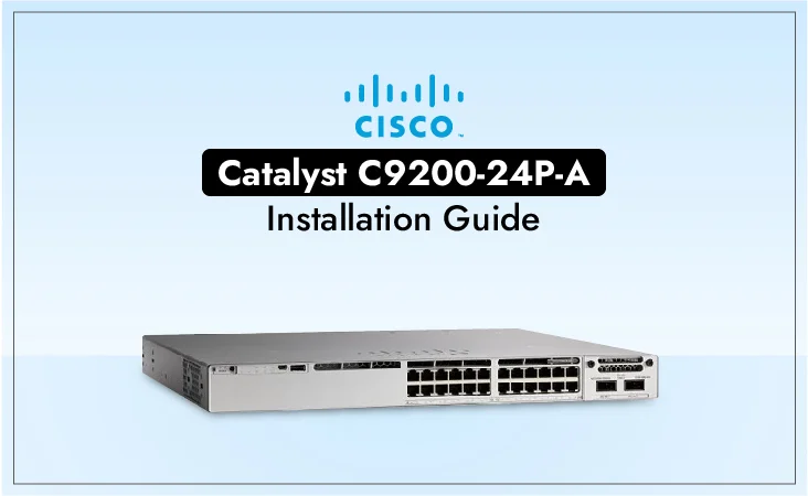
3If you are looking to upgrade your network infrastructure with top of the line advanced Cisco technology, you're at the right place. Welcome to our comprehensive guide to installing the Cisco Catalyst C9200-24P-A switches. In this article, we provide you with clear, step-by-step instructions on how to set up this modern switch model. Whether you're an IT professional or new to networking, our guide will ensure a smooth installation process, allowing you to maximize the potential of your network with ease and confidence. Let's get started optimizing your network with the Cisco Catalyst 9200 series switches.
Cisco Catalyst 9200 series switches represent the next generation of enterprise-class stackable access-layer switches. Among these, the Cisco Catalyst C9200-24P-A stands out for its powerful performance and advanced features. Designed to meet the demands of modern networking environments, it offers a range of capabilities to support various applications and workloads.
Cisco Catalyst C9200-24P-A is a feature-rich switch designed to meet the evolving needs of modern networking environments. With support for Power over Ethernet (PoE), it simplifies installation by providing both power and data over a single Ethernet cable, reducing clutter and streamlining connectivity. Additionally, its compatibility with Cisco DNA enables advanced network automation and analytics, allowing organizations to optimize performance and enhance operational efficiency. The switch's modular design ensures easy scalability, making it ideal for businesses looking to expand their network infrastructure without hassle. With robust security features and high-performance capabilities, the Cisco Catalyst C9200-24P-A offers unparalleled reliability and versatility for a wide range of deployment scenarios.
Table 1 enlists the features and benefits of these Cisco Catalyst switches in some detail below:
|
Feature |
Benefit |
|
Power over Ethernet (PoE) |
Simplifies installation by providing power and data over a single Ethernet cable. |
|
Cisco DNA Support |
Enables advanced network automation and analytics for enhanced performance. |
|
Modular Design |
Allows for easy scalability and future expansion of network infrastructure. |
|
Advanced Security |
Offers robust security features to protect against cyber threats and attacks. |
|
High Performance |
Delivers reliable and high-speed connectivity to support demanding applications. |
|
Flexible Deployment |
Can be deployed in various environments, including enterprise and branch offices. |
The Cisco 9200 series offers a range of switch models designed to meet the diverse needs of businesses. The C9200 switches provide options such as PoE support and enhanced features, making them suitable for various deployment scenarios. On the other hand, the C9200L switches offer Gigabit Ethernet connectivity with options for different uplink configurations, providing flexibility and scalability for network expansion. Whether you need high-speed connectivity, PoE capabilities, or enhanced features, the Cisco 9200 series has a switch model to fit your requirements. Table 2 highlights some key switch models of c9200 series switches:
|
Model |
Description |
|
48-port PoE switch |
|
|
48-port non-PoE switch |
|
|
24-port non-PoE switch with enhanced features |
|
Model |
Description |
|
48-port Gigabit Ethernet switch with 4 Gigabit SFP uplinks |
|
|
48-port Gigabit Ethernet switch with 4 10 Gigabit Ethernet uplinks and enhanced features |
|
|
48-port Gigabit Ethernet switch with 4 10 Gigabit Ethernet uplinks |
This section describes the front panel components of Cisco Catalyst 9200 Series switches :
|
1 |
Blue Beacon (UID button) |
|
2 |
Mode button |
|
3 |
Status LEDs |
|
4 |
USB mini-Type B (console) port |
|
5 |
USB Type A storage ports |
|
6 |
10/100/1000 PoE+ ports |
|
7 |
Fixed uplink ports |
|
1 |
Blue Beacon (UID button) |
|
2 |
Mode button |
|
3 |
USB mini-Type B (console) port |
|
4 |
USB Type A storage ports |
|
5 |
10/100/1000 PoE+ ports |
|
6 |
Network Module with uplink ports |
|
1 |
Module slot |
|
2 |
LEDs |
Table 3 lists the optional Cisco Catalyst 9200 Series Switches uplink network modules with 4x1G, 4x10G, 2x25G, and 2x40G slots:
|
Network Module |
Description |
|
C9200-NM-4X |
4-port multigigabit Ethernet network module |
|
C9200-NM-2Q |
2-port 40 Gigabit Ethernet (QSFP+) network module |
|
C9200-NM-4GE |
4-port Gigabit Ethernet network module |
|
C9200-NM-2X |
2-port 10 Gigabit Ethernet (SFP+) network module |
|
C9200-NM-8X |
8-port 10 Gigabit Ethernet (SFP+) network module |
These network modules provide additional connectivity options and expansion capabilities for Cisco 9200 switches, allowing organizations to tailor their network infrastructure to specific requirements and scale as needed. Whether you need high-speed multigigabit Ethernet ports, 40 Gigabit Ethernet uplinks, or additional Gigabit Ethernet or 10 Gigabit Ethernet ports, there's a network module available to meet your needs.
The switch includes a field replaceable primary AC power supply module and a redundant hot-swappable field replacement AC power supply module. In switches with PoE capabilities, the redundant power supply can also be utilized to provide additional PoE power.
The following are the power supply modules supported on Cisco Catalyst 9200 Series Switches:
The switch has two internal power supply module slots. You can use two AC power supply modules or one power supply module and a blank module (PWR-C5-BLANK). Furthermore, this switch has two internal power supply module slots. You can use two AC power supply modules or one power supply module and a blank module (PWR-C5-BLANK).
Read More: Cisco Catalyst vs Aruba: Budget-Friendly Networking
Before proceeding with the installation of the Cisco Catalyst C9200-24P-A, it's essential to gather all the necessary equipment and tools. This includes the switch itself, mounting brackets, screws, power cables, and any additional peripherals required for the setup. In order to avoid mishaps and guarantee a seamless installation procedure, it is also essential to follow safety protocols.
When determining where to install the switch, verify that these guidelines are met: • Clearance to the switch front and rear panels meets these conditions:
Planning a proper location for the switch and layout of the equipment rack or wiring closet is essential for successful system operation. These sections describe some of the basic site requirements that you should be aware of as you prepare to install your switch, including the following:
Once you've gathered all the required equipment, it's time to begin the physical installation of the Cisco Catalyst C9200-24P-A. Start by carefully unboxing the switch and inspecting it for any signs of damage. Next, determine the appropriate mounting option based on your specific requirements and available space. Whether you choose to rack-mount or wall-mount the switch, ensure that it is securely fastened to prevent any accidents.
The shipping box contains the model of the Cisco switch you ordered and other components needed for installation. Some components are optional, depending on your order. Visit ORM Systems and get these essentials when you order C9200 Switches
|
1 |
Cisco Catalyst 9200 Series switch (power supply modules are not displayed) |
|
2 |
AC power cord |
|
3 |
Four rubber mounting feet |
|
4 |
Two 19-inch mounting brackets |
|
5 |
4 number-12 pan-head screw |
|
6 |
4 number-10 pan-head screws |
|
7 |
8 number-8 Phillips flat-head screws |
|
8 |
Cable guide |
|
9 |
M4.0 x 20mm Phillips pan-head screw |
|
10 |
RJ-45 USB console cable |
|
11 |
(Optional) USB console cable |
|
12 |
(Optional) StackWise cable (0.5-meter, 1-meter, or 3-meter) |
|
13 |
Power cord retainer |
The following sections explain the different mounting options available for the Cisco Catalyst C9200-24P-A switch:
Powering up a switch involves several steps to ensure a smooth and safe operation. Here's a detailed explanation of each step:
Before powering up the switch, verify that the power source (such as a power outlet or power supply unit) is working correctly and providing the appropriate voltage.
Inspect the switch for any visible damage or defects. Check the power cable and connectors for any signs of wear or damage.
Connect one end of the power cable to the power input port on the switch. Ensure that the connector is securely plugged in to prevent accidental disconnection.
Plug the other end of the power cable into a nearby power outlet. Make sure that the outlet is easily accessible and that there are no obstructions blocking access to the switch.
Locate the power button or switch on the switch chassis. Press the power button or toggle the power switch to the "on" position. Some switches may have a power LED indicator that lights up when the switch is powered on.
After powering on the switch, observe the LED indicators on the front panel. These indicators provide valuable information about the status of various components, such as power, system health, and network connectivity. Verify that the power LED is lit and that there are no error indicators illuminated.
Depending on the switch model and configuration, the switch may take some time to complete its boot-up sequence. During this time, the switch performs self-tests and initializes its hardware and software components. Be patient and allow the switch sufficient time to complete the boot-up process.
Once the switch has completed its boot-up sequence, verify that it is operating correctly. Check the console or management interface for any error messages or warnings. Test network connectivity by connecting devices to the switch ports and verifying that they can communicate with each other.
Finally, document the switch installation, including the serial number, location, and any relevant configuration details. This information will be useful for future reference and troubleshooting.
By following these steps, you can safely and effectively power up a switch and ensure reliable operation in your network infrastructure.
Once the initial configuration is complete, proceed with the network configuration. This involves setting up VLANs, assigning IP addresses to interfaces, and configuring port settings to ensure optimal performance and security. Depending on your specific requirements, you may also need to configure additional features such as Quality of Service (QoS) and port security.
Read more: Cisco Catalyst 9200 Switches vs Aruba 2930M Switches: Comparing Prices
Table 4 describes the environmental specifications:
|
Environmental Ranges |
|
|
Operating temperature |
23 to 113°F (–5 to 45°C) |
|
Storage temperature |
–40 to 158°F (–40 to 70°C) |
|
Relative humidity |
5 to 90% (non condensing) |
|
Operating altitude |
Up to 10,000 ft (3000 m) |
|
Storage altitude |
Up to 15,000 ft (4500 m) |
The minimum ambient temperature for a cold start is 32°F (0°C).
Table 5 describes the environmental specifications.
|
Environmental Ranges |
|
|
Operating temperature |
23°F to 113°F (–5°C to 45°C) up to 5000 feet (1500m) 23°F to 104°F (–5°C to 40ºC) up to 10,000 feet (3000m) |
|
Storage temperature |
–40 to 158°F (–40 to 70°C) |
|
Relative humidity |
5% to 90% (non condensing) |
|
Altitude |
10,000 ft (3,000 m) up to 45°C |
Table 6 describes the physical specifications down below:
|
Dimensions (H x W x D) |
|
|
Chassis Dimensions |
Chassis Dimensions with the FAN FRUs and the power supplies installed |
|
1.73 x 17.5 x 13.8 in. (4.4 x 44.4 x 35 cm) C9200-24P |
1.73 x 17.5 x 15.4 in. (4.4 x 44.4 x 39.1 cm) C9200-24P |
|
1.73 x 17.5 x 13.8 in. (4.4 x 44.4 x 35 cm) C9200-24PB |
1.73 x 17.5 x 15.4 in. (4.4 x 44.4 x 39.1 cm) C9200-24PB |
|
1.73 x 17.5 x 13.8 in. (4.4 x 44.4 x 35 cm) C9200-48P |
1.73 x 17.5 x 15.4 in. (4.4 x 44.4 x 39.1 cm) C9200-48P |
|
1.73 x 17.5 x 13.8 in. (4.4 x 44.4 x 35 cm) C9200-48PB |
1.73 x 17.5 x 15.4 in. (4.4 x 44.4 x 39.1 cm) C9200-48PB |
|
1.73 x 17.5 x 13.8 in. (4.4 x 44.4 x 35 cm) C9200-48PL |
1.73 x 17.5 x 15.4 in. (4.4 x 44.4 x 39.1 cm) C9200-48PL |
|
1.73 x 17.5 x 13.8 in. (4.4 x 44.4 x 35 cm) C9200-48T |
1.73 x 17.5 x 15.4 in. (4.4 x 44.4 x 39.1 cm) C9200-48T |
|
1.73 x 17.5 x 13.8 in. (4.4 x 44.4 x 35 cm) C9200-24PXG |
1.73 x 17.5 x 15.4 in. (4.4 x 44.4 x 39.1 cm) C9200-24PXG |
|
1.73 x 17.5 x 13.8 in. (4.4 x 44.4 x 35 cm) C9200-48PXG |
1.73 x 17.5 x 15.4 in. (4.4 x 44.4 x 39.1 cm) C9200-48PXG |
|
1.73 x 17.5 x 11.3 in. (4.4 x 44.5 x 28.8 cm) C9200L-24P-4G |
1.73 x 17.5 x 12.9 in. (4.4 x 44.5 x 32.9 cm) C9200L-24P-4G |
|
1.73 x 17.5 x 11.3 in. (4.4 x 44.5 x 28.8 cm) C9200L-24P-4X |
1.73 x 17.5 x 12.9 in. (4.4 x 44.5 x 32.9 cm) C9200L-24P-4X |
|
1.73 x 17.5 x 11.3 in. (4.4 x 44.5 x 28.8 cm) C9200L-24T-4G |
1.73 x 17.5 x 12.9 in. (4.4 x 44.5 x 32.9 cm) C9200L-24T-4G |
|
1.73 x 17.5 x 11.3 in. (4.4 x 44.5 x 28.8 cm) C9200L-24T-4X |
1.73 x 17.5 x 12.9 in. (4.4 x 44.5 x 32.9 cm) C9200L-24T-4X |
|
1.73 x 17.5 x 11.3 in. (4.4 x 44.5 x 28.8 cm) C9200L-48P-4G |
1.73 x 17.5 x 12.9 in. (4.4 x 44.5 x 32.9 cm) C9200L-48P-4G |
|
1.73 x 17.5 x 11.3 in. (4.4 x 44.5 x 28.8 cm) C9200L-48P-4X |
1.73 x 17.5 x 12.9 in. (4.4 x 44.5 x 32.9 cm) C9200L-48P-4X |
|
1.73 x 17.5 x 11.3 in. (4.4 x 44.5 x 28.8 cm) C9200L-48PL-4G |
1.73 x 17.5 x 12.9 in. (4.4 x 44.5 x 32.9 cm) C9200L-48PL-4G |
|
1.73 x 17.5 x 11.3 in. (4.4 x 44.5 x 28.8 cm) C9200L-48PL-4X |
1.73 x 17.5 x 12.9 in. (4.4 x 44.5 x 32.9 cm) C9200L-48PL-4X |
|
1.73 x 17.5 x 11.3 in. (4.4 x 44.5 x 28.8 cm) C9200L-48T-4G |
1.73 x 17.5 x 12.9 in. (4.4 x 44.5 x 32.9 cm) C9200L-48T-4G |
|
1.73 x 17.5 x 11.3 in. (4.4 x 44.5 x 28.8 cm) C9200L-48T-4X |
1.73 x 17.5 x 12.9 in. (4.4 x 44.5 x 32.9 cm) C9200L-48T-4X |
|
1.73 x 17.5 x 13.8 in. (4.4 x 44.5 x 35 cm) C9200L-24PXG-4X |
1.73 x 17.5 x 15.4 in. (4.4 x 44.5 x 39.1 cm) C9200L-24PXG-4X |
|
1.73 x 17.5 x 13.8 in. (4.4 x 44.5 x 35 cm) C9200L-24PXG-2Y |
1.73 x 17.5 x 15.4 in. (4.4 x 44.5 x 39.1 cm) C9200L-24PXG-2Y |
|
1.73 x 17.5 x 13.8 in. (4.4 x 44.5 x 35 cm) C9200L-48PXG-4X |
1.73 x 17.5 x 15.4 in. (4.4 x 44.5 x 39.1 cm) C9200L-48PXG-4X |
|
1.73 x 17.5 x 13.8 in. (4.4 x 44.5 x 35 cm) C9200L-48PXG-2Y |
1.73 x 17.5 x 15.4 in. (4.4 x 44.5 x 39.1 cm) C9200L-48PXG-2Y |
Weight measurement is calculated with one power supply installed.
|
Switch Model |
Weight |
|
C9200-24T |
11 lb (5 kg) |
|
C9200-24P |
11 lb (5 kg) |
|
C9200-24PB |
11 lb (5 kg) |
|
C9200-48T |
11.5 lb (5.2 kg) |
|
C9200-48P |
11.5 lb (5.2 kg) |
|
C9200-48PB |
11.5 lb (5.2 kg) |
|
C9200-48PL |
11.5 lb (5.2 kg) |
|
C9200-24PXG |
11.4 lb (5.15 kg) |
|
C9200-48PXG |
11.9 lb (5.44 kg) |
|
C9200L-24T-4G |
9.6 lb (4.35 kg) |
|
C9200L-24P-4G |
10.4 lb (4.71 kg) |
|
C9200L-48T-4G |
10 lb (4.53 kg) |
|
C9200L-48P-4G |
10.6 lb (4.8 kg) |
|
C9200L-48T-4X |
10 lb (4.53 kg) |
|
C9200L-48P-4X |
10.6 lb (4.8 kg) |
|
C9200L-24P-4X |
10.4 lb (4.71 kg) |
|
C9200L-24T-4X |
9.6 lb (4.35 kg) |
|
C9200L-48PL-4G |
10.6 lb (4.8 kg) |
|
C9200L-48PL-4X |
10.6 lb (4.8 kg) |
|
C9200L-24PXG-4X |
12 lb (5.44 kg) |
|
C9200L-24PXG-2Y |
12 lb (5.44 kg) |
|
C9200L-48PXG-4X |
12.6 lb (5.71 kg) |
|
C9200L-48PXG-2Y |
12.6 lb (5.71 kg) |
Table 7 describes the physical specifications:
|
Weight |
|
|
PWR-C5-125WAC |
1.5 lb (0.68 kg) |
|
PWR-C5-600WAC |
1.7 lb (0.77 kg) |
|
PWR-C5-1KWAC |
2 lb (0.9 kg) |
|
PWR-C6-125WAC |
1.5 lb (0.68 kg) |
|
PWR-C6-600WAC |
1.7 lb (0.77 kg) |
|
PWR-C6-1KWAC |
2 lb (0.9 kg) |
|
Dimensions (H x D x W) The dimensions shown include the extraction handle and the keying feature. |
|
|
PWR-C5-125WAC |
1.58 x 4.0 x 7.6 in. (40.1 X 101.6 X 193 mm) |
|
PWR-C5-600WAC |
|
|
PWR-C5-1KWAC |
|
|
PWR-C6-125WAC |
|
|
PWR-C6-600WAC |
|
|
PWR-C6-1KWAC |
|
Looking to purchase Cisco Catalyst 9200 series switches but unsure where to buy them at an affordable price? Look no further than ORM Systems, your one-stop shop for high-quality networking equipment. Our competitive prices and a wide selection of Cisco 9200 switch models make it easy to find the perfect solution for your networking needs. Whether you're looking for a specific model or need assistance choosing the right switch for your requirements, our knowledgeable sales team is here to help. Don't let high prices hold you back from upgrading your network infrastructure; shop with confidence at ORM Systems and get the best value for your investment in Cisco Catalyst 9200 series switches.
Want to buy this series of products? please contact:
ORM Systems is a global IT hardware and software solution provider. Our core focus is providing authentic, reliable, and cost-effective IT hardware products along with enterprise software solutions. Our superior customer service team has built a strong correlation between our customers and suppliers. We have laid out our physical presence by having operational branches and warehouses in the UK, USA, Europe and the Middle East. We stock huge inventory globally and provide fast delivery, an absolute supply chain and logistics for our consumers all around the world, with a guarantee of meeting your standard requirements.
Transceivers:
Power Supplies:
In conclusion, the Cisco Catalyst C9200-24P-A is a versatile and reliable switch that offers advanced features and robust performance. By following the installation guide provided, organizations can quickly and easily deploy this switch in their network infrastructure, enabling them to take advantage of its numerous benefits and capabilities.
Related Topics:
What Makes the Cisco Catalyst C9200-24P-A Switch Ideal for Medium-Sized Businesses?
Managed vs Unmanaged Switches: How to Choose the Best Network Switch
Cisco 9200 VS 9300 series switches: Head-to-Head Comparison
Q. What is the warranty period for the Cisco Catalyst C9200-24P-A?
A. Cisco Catalyst C9200-24P-A comes with a standard warranty period of 3 years.
Q. Can I stack multiple Cisco Catalyst 9200 switches?
A. Yes, Cisco Catalyst 9200 switches support stacking to expand capacity and improve resiliency.
Q. Is technical support available for installation assistance?
A. Yes, Cisco offers technical support services to assist with installation and configuration.
Q. Are there any compatibility issues with third-party accessories?
A. Cisco Catalyst 9200 switches are designed to work seamlessly with Cisco-approved accessories. However, it's recommended to use genuine Cisco accessories for optimal performance and compatibility.
Q. How can I upgrade the firmware of the Cisco Catalyst C9200-24P-A?
A. Firmware upgrades for Cisco Catalyst C9200-24P-A can be performed using the Cisco IOS Software Command-Line Interface (CLI) or Cisco DNA Center.
Recent Posts
Nexus 7010 vs 7710: Comprehensive Analysis
29 May, 2024
Migrating from Nexus 7000 to 9000
28 May, 2024
How to Use Cisco Commands for Network Diagnosis?
27 May, 2024

Cisco Competitors: Top Picks for 2024
23 May, 2024

Cisco ASA Firewall: Key Features for Business
22 May, 2024
Most Used Tags

Developing performance-driven networks to boost the efficiency of your business

Thank you for your interest in ORM systems, our experts will connect with you shortly.


